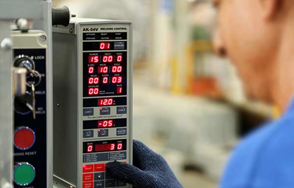
While using current monitor you need to feed upper and lower limit to the controller. This can be done as under :
Example:
Suppose your part requires 10 KA current for 8 cycle .
And your setting is as under
| 30 | 00 | 0 | 0 | 00 | 0 | 08 | 0 | 5 | 0 |
| sq | Weld1 | Co1 | Sl1 | We2 | Co2 | We3 | Sl2 | hold | off |
And
| 0 | 10 | 0 |
| Curr1 | Curr2 | Curr3 |
(Insure you are putting value in curr2, This can be done by pressing curr2 button and insuring the LED over the button is glowing. Also insure values in curr1 and curr3 by pressing respective buttons. If there is value in weld 1 , it corresponds to curr1 ; value in weld2 and weld3 corresponds to curr2 and curr3 respectively. If you put some value in weld1 and ‘0’ in curr1 this will result in error)
- This setting means you need 10 KA current for good weld.
- Press “MONITOR DISPLAY” button, insure the LED on the button is glowing.
Monitor display ON will give you actual current flown during the process this value will be displayed at window immediately above the “curr2 “ button. Its percentage over set value of current will be displayed at the window above “monitor display button.
- Observe actual current flown ,displayed in the window, and its percentage over set value(10KA)
If the % difference is better than +/- 5%, Your setting time is OK ( else try to increase weld time).
Make destructive test and confirm parameters OK for weld strength. After getting OK result move for next step. - Calculate 10 % less of the set value (i.e. 9 KA)
- Set 09.0 KA in curr2 window.
Make a weld
Observe actual current drawn.
Make destructive test for weld strength. - If the test is ok we can conclude 9KA current is also OK for making good weld.¨C15C If you get test fails, increase default value and repeat the procedure or insure your self, by trial and error correct lower value of current.¨C16C ¨C17C
- Accordingly set upper value and calculate safe % of upper limt.
- In this example Now we have
9 KA as lower limit .( 10% lower)
10 KA set value
10.5 KA as upper limit ( 5% high )
Now we can set upper and lower limit on controller monitor.
- Push ‘prog’ button
Push lower limit button (- % limit)
Enter 10 - Push upper limit ( +% limit)
Enter 05
Push prog again
Now the controller is programmed for upper and lower limits.
- It will give alarm (error output) at the instant the actual current fall beyond the go – nogo limit.
Error alarm can be reset by pressing error reset button.
There are few other errors related to setting and maintenance of the controller . Please read the error no. details from the manual page 36.
- We can also use other powerful function built in like –
– electrode wear compensation
– Multiple program calling
– Interlocking with other inputs.
– Computer interfacing for data download
Please read Manual for details.


